Development length (Ld) is the length of reinforcement that must be embedded in concrete beyond a critical section so that the design stress in the bar can be transferred to the concrete through bond.
In other words, (Ld) is the extra length of bar beyond the point of maximum stress to ensure it does not pull out under loading.
IS 456:2000 (Clause 26.2.1) states that “the calculated tension or compression in any bar at any section shall be developed on each side of the section by an appropriate development length or end anchorage”.
In practice, this means the bar must extend a minimum distance into the concrete so that the bond shear stresses (from adhesion and interlock) can carry the steel force.
If a bar is too short, the reinforcement will pull out and the member will fail in a brittle bond failure rather than in ductile steel yielding.
Development length is a critical design parameter in beams, columns, footings, and slabs wherever bars must be anchored (e.g., at beam supports or at column-foundation connections).
Insufficient (Ld) can lead to cracking, excessive deflection, or even collapse. CivilEek’s Development Length Calculator enforces IS 456:2000 rules and helps avoid such failures.
Definition of Development Length
Formally, development length is defined (by IS 456:2000) as “the embedment needed to develop the design stress in the bar through bond with the surrounding concrete”.
In simpler terms, it is the length of bar required to safely transfer the steel’s tensile or compressive force into the concrete.
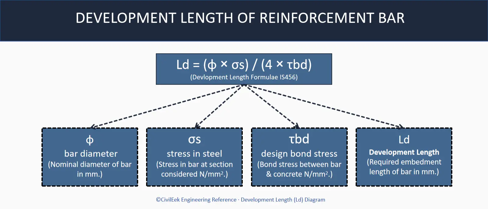
This is achieved by bond stress (τbd) acting along the interface. For a steel bar with diameter (φ) and stress (σs), the tensile force is (P = σs (π2/4)). Assuming an average bond stress (τbd) along length (Ld), equilibrium of forces gives:
σs × (πφ²/4) = τbd × (πφLd)
Ld = (φ × σs) / (4 × τbd)
This derivation (equating steel force to bond force) leads to the IS 456 formula below. Note that this length includes any additional anchorage provided by hooks or bends on a tension bar (see Note 1 of Clause 26.2.1). In other words, if a U-hook is provided, its equivalent length contributes to (Ld).
Formula for Development Length
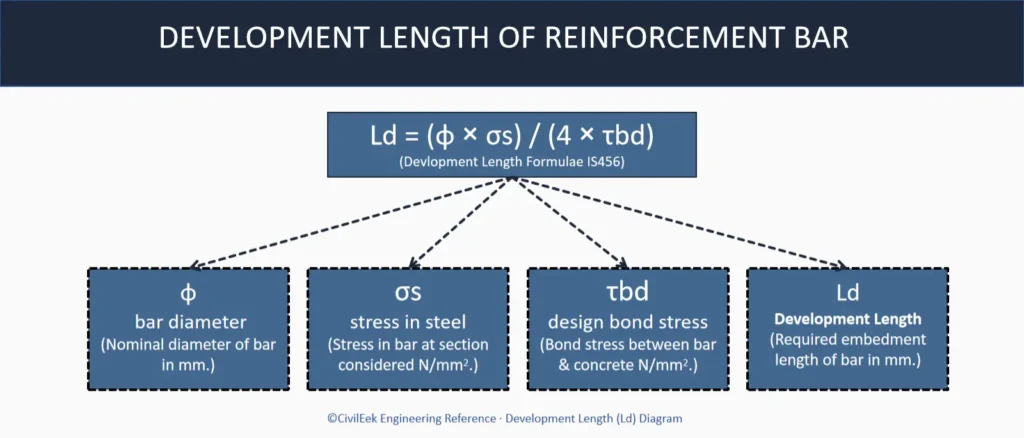
IS 456:2000 Clause 26.2.1 specifies the development length formula as:
Ld = (φ × σs) / (4 × τbd)
where:
- φ = nominal diameter of the bar (mm),
- σs = stress in the bar at the section under design loads (N/mm²), and
- τbd = design bond stress for the given concrete grade (N/mm²).
For limit-state (ultimate) design in tension, steel stress is usually taken as σs = 0.87 fy (where (fy) is the characteristic yield strength).
In compression zones, the bar stress may be less, but conservatively the same σs=0.87fy is often used (or proportionally less). Substituting σs and τbd into the formula yields Ld in millimeters.
Example formula application: for a 20 mm bar with σs=435 MPa and (τbd=1.92) MPa (as in the example below), the development length is
Ld = (20 × 435) / (4 × 1.92) = 1132.8 mm
(This matches with Development Length Calculation Example below)
Bond Stress Values as per IS 456
The key input in the formula is the design bond stress (τbd), which depends on concrete strength and bar type. IS 456:2000 Table 26.2.1.1 (Clause 26.2.1.1) gives (τbd) for plain bars in tension. For common concrete grades:
| Concrete Grade | Plain Bars (τbd) [N/mm²] | Deformed Bars (τbd) [N/mm²] |
|---|---|---|
| M20 | 1.2 | 1.92 (≈1.2×1.6) |
| M25 | 1.4 | 2.24 |
| M30 | 1.5 | 2.40 |
| M35 | 1.7 | 2.72 |
| M40 & above | 1.9 | 3.04 |
As per IS 456, deformed (TMT) bars get a 60% higher bond stress than plain bars. Thus (τbd) for deformed bars is the plain value ×1.6 (as shown in the table). For example, plain bars in M20 have (τbd=1.2) MPa, so deformed bars in M20 have (1.2\times1.6 =1.92) MPa.
In bars under compression, code allows an increased bond stress as well: Clause 26.2.1.1 specifies that compression bars may use 25% higher (τbd) (i.e. multiply the tension value by 1.25). Equivalently, one can compute (Ld) in compression as (0.8Ld) (no shorter than 200 mm).
Development Length Calculation Example
Given: Concrete = M20, Steel = Fe500, Bar diameter (φ=20) mm, Bar type = deformed, Stress case = tension (usual case in beams).
- Concrete grade ⇒ bond stress: From Table 26.2.1.1, plain-bar bond stress for M20 is (τbd_plain=1.20) N/mm². For a deformed (TMT) bar, increase by 60%: (τbd = 1.20 \times 1.6 = 1.92) N/mm².
- Steel stress (σs): For Fe 500, design stress = (0.87f_y = 0.87\times500 = 435) N/mm².
- Apply formula:
Ld = (φ × σs) / (4 × τbd) = (20 mm × 435 N/mm²) / (4 × 1.92 N/mm²) = 1132.8 mm - Final answer: (Ld ≈ 1133) mm (rounded). In terms of bar diameters, this is (1133/20 ≈ 56.7φ).
Development Length for Plain and Deformed Bars
Deformed bars (ribbed/TMT) achieve better bond than smooth plain bars, so they require shorter development lengths. As shown above, increasing (τbd) by 60% (factor of 1.6) for a deformed bar reduces (Ld) to (1/1.6) of the plain-bar value.
For example, the plain-bar (Ld) for Fe500, M20, 20mm is
Ld,plain = (20 × 435) / (4 × 1.20)
Ld,plain = 1812.5 mm
which is about 1800 mm. By contrast, the deformed bar (Ld) we calculated is 1133 mm – roughly 60% as long.
| Bar Type | (τbd) (M20) [N/mm²] | (Ld) (20 mm bar) [mm] |
|---|---|---|
| Plain (Fe500) | 1.20 | 1813 |
| Deformed (Fe500) | 1.92 | 1133 |
In design, deformed bars typically do not require hooks for anchorage if the full (Ld) can be provided straight. By contrast, plain (mild) bars have weaker bond; IS 456 notes that “Hooks should normally be provided for plain bars in tension”. In practice, if a plain bar’s straight embedment is limited, a 90° bend or U-hook may be required to attain the effective (Ld).
Development Length in Tension and Compression
The formula above was applied for a tension bar. For compression reinforcement, IS 456 permits a reduction: clause 26.2.1.1 allows a 25% shorter development length (equivalently, 25% higher bond stress) for bars in compression.
In effect: Ld,compression = 0.8 × Ld,tension with the proviso that the compressive development length shall not be less than 200 mm. This reduction is allowed because cracking is less severe in compression, so bond can be relied on more.
Key points:
- For tension bars, use (Ld) as calculated. Typically these are bottom bars in beams or column ties.
- For compression bars (e.g. top bars at mid-span, or bottom bars under support), use (0.8Ld) (but ≥200 mm).
- Ensure units are consistent (mm and N/mm² as above) and round (Ld) up to the next whole number or at least to the next bar diameter, since partial bars don’t exist.
Practical Applications
In real structures, development length governs many detailing decisions:
- Beams and Slabs: The tension steel over supports (negative moment reinforcement) must extend into the support by at least (Ld) or by a hook. Likewise, bottom bars in cantilevers and slabs must meet (Ld) into the supporting concrete. If a beam or slab is simply supported, the bottom bars should extend (Ld) from the face of support towards mid-span. In frames, rebar that continues into an adjacent column or beam must provide (Ld) past the joint.
- Columns: Longitudinal column bars anchoring into slabs or footings need (Ld). For example, if a 20 mm beam bar requires 1133 mm in M20 concrete (as calculated), but the adjacent column is only 230 mm wide, it is impractical to embed the bar straight. In such cases, a 90° bend or U-hook is used. IS 456 provides the anchorage values for bends and hooks (see below). A standard 90° hook (with 8φ anchorage) or 180° U-hook (16φ) can substitute for straight length when space is limited.
- Footings/Bases: Column bars extending down into footings must provide (Ld) in the footing to achieve their full capacity. If the footing is shallow, hooks or anchors may be required. Similarly, dowels from shear walls or footings must meet development requirements.
- Reinforcement Bundles: If bars are bundled (2 or more touching), each bar’s (Ld) is increased by 10% per extra bar (10% for 2 bars, 20% for 3 bars, etc.), since bonding surface is reduced. This should be checked in congested areas.
- Hooks and Bends: The code gives anchorage equivalences: each 45° bend provides (4φ) of length (up to a max of (16φ)), and a full 180° U-hook provides (16φ). For example, a standard U-hook (180°) on a bar is taken as 16 times the bar diameter in anchorage length. These allow bars to “grab” into the concrete. (Concrete cover must be adequate for the bearing pressure inside the bend.)
Common Mistakes
Even experienced designers can slip up on development length. Common errors include:
- Forgetting the TMT factor: Using the plain-bar (τbd) instead of multiplying by 1.6 for deformed (Fe 500/550) bars. This makes (Ld) about 60% too large. Always apply the 60% increase for deformed bars.
- Using wrong steel stress: Using (fy) instead of (0.87fy) for (σs) in the formula (for limit-state). This underestimates (Ld). For plastic hinge (seismic) regions, IS 13920 requires using full (fy), but for ordinary L.S. design use (0.87fy).
- Ignoring section location: Calculating (Ld) from the wrong point. The length should extend from the critical section where stress is maximum. For example, at an end support, (Ld) must start at the face of support or section of contraflexure, not from the column edge.
- Rounding down: Always round (Ld) up to a whole number (or to the nearest bar diameter). Designers often round down and underestimate required length.
- Unit mistakes: Mixing mm with cm or forgetting units can cause big errors (e.g. 1133 mm ≠ 1133 cm!). Keep units consistent (N/mm² and mm).
- Neglecting compression rule: Applying tension (Ld) to compression bars. For top bars, remember to use the 0.8 factor (compression (Ld) is shorter).
By checking these points (some of which are automated in the CivilEek Excel tool), one can avoid most errors.
FAQs
Q: Is anchorage length the same as development length?
A: In IS 456 terminology, development length is the general term, and it includes any anchorage from bends or hooks on a tension bar. So in practice they are used interchangeably for tension reinforcement. However, “anchorage length” sometimes refers specifically to a hooked or bent end. In effect, providing the required development length (via straight embedment plus any hooks) ensures adequate anchorage per code.
Q: Can hooks or bends reduce the required (Ld)?
A: Yes. Per IS 456 clause 26.2.2.1, hooks and bends contribute to (Ld). For instance, a 45° bend gives the equivalent of (4φ) of straight development, a 90° bend (8φ), and a U-hook (180°) (16φ). In practice, if space is limited (e.g. in a thin column), a hook is used so that some of the required (Ld) is provided by the hook. However, even with a hook, the bar must still have enough straight embedment plus hook to equal the full (Ld). (IS 2502 specifies how bends and hooks should be formed.)
Q: What is the minimum development (anchorage) length?
A: IS 456 does not give a separate minimum (Ld) for tension bars beyond the formula. Some practices use a rule of thumb (e.g. at least (12φ) or 150 mm) to ensure practical anchorage, but this is not codified. For bars in compression, IS 456 explicitly says the reduced (Ld) must not be less than 200 mm. Also note that any hook must meet standard dimensions (a 90° hook provides (8φ), a 135° hook (12φ), etc. as per clause 26.2.2.1).
Download Free Excel Calculator
For convenience, a free Excel tool “Development Length Calculator (IS 456:2000)” (CE-XL-IS-RCC-001, v1.0) is available.
This spreadsheet lets you enter: concrete grade (M20–M50), steel grade (Fe415, Fe500, Fe550), bar diameter (in mm), bar type (plain or deformed), and whether the bar is in tension or compression.
It outputs the required development length (Ld) (in mm and as a multiple of bar diameter) and flags any invalid inputs.
The tool automatically uses the IS 456 bond stress table and factors for deformed bars, and applies the 0.8 factor for compression. (User must still verify results in context.)